Tutorials
This tutorial aims at giving important steps of the use of « Bloc Fissure ». Those steps are the standard procedure that the user should apply to avoid « Bloc Fissure » failure and unexpected problem in the modelisation afterwards.
First, the user should ask himself if its case is compatible with « Bloc Fissure ». See the section on limitations.
Convert elements from quadratic to linear
Mesh Module: Modification > Convert to/from quadratic
Change the orientation of all faces to set them to outgoing
Mesh Module: Modification > Reorient faces
Verify that the crack exceeds everywhere from the structure. If it’s not the case, move or extend the crack geometry.
Verify that the crack front edges don’t stop right at the Box surface.
Here is some advice :
To move the crack:
GEOM Module: Operations > Transformation > Translation
- First way to extend the crack geometry in GEOM module:
Operations > Explode: Choose the crack geometry and explode into Edges
Operation > Transformations > Extension: extend the length of the crack edges
Rebuild edges to get a closed group of edges exceeding from the structure
New Entity > Build > Wire: Create a wire from the edges
New Entity > Build > Face: Create a face from the wire
Get the new crack front edge number
|
|
|
|
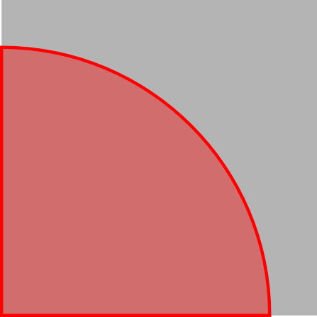
Initial bad crack geometry |
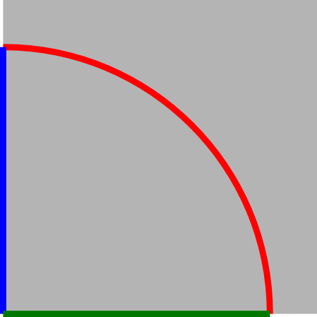
Explode face into edges |
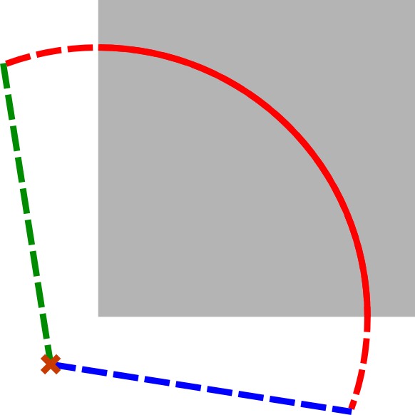
Extend front edge and rebuild wire |
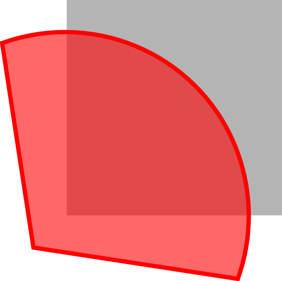
Rebuild crack face |
- second way to extend the crack geometry in GEOM module:
Create new surfaces linked to the original crack geometry
Fuse the surfaces to get an extended crack
Execute the « Bloc Fissure » script and check that it ended successfully.
Reorient faces to outgoing normal
Rebuild groups impacted by crack insertion
Export the cracked mesh